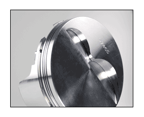
Ross Racing Pistons
TECH SUPPORT
Tips on commonly asked technical questions, piston & ring installation guides, order forms and more.
How To Create Combustion Chamber Molds
- Clean both the chamber and head surface; chamber must be free of all dirt, oil and grease, and valves must be installed.
- Place cylinder head properly on the block using no head gaskets. Snug cylinder head bolts or studs with dowel pins installed. Turn block over until cylinder head is facing downward toward the floor. Cylinder head deck must be level before pouring mold.
- Insert plastic plug, or other stopper, into spark plug hole on the chamber side. Tap in if needed.
- Spray both the chamber and cylinder bore with WD40 or wipe down with a light coat of oil or silicone spray.
- Mix epoxy or Bondo as per manufacturer’s instructions.
- Pour mixture into combustion chamber from the bottom of block until epoxy covers at least .250” (6.5 mm) up of the cylinder bore from the head surface.
- Let epoxy or Bondo cure as per instructions that came with product. Once epoxy or Bondo has hardened, flip engine right side up and remove cylinder head.
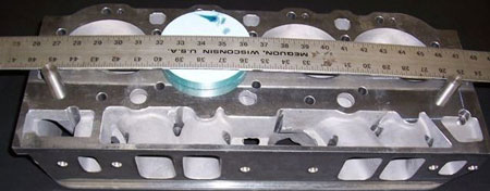
- Before removing chamber mold from cylinder head, install dowel pins into cylinder head. Place a straight edge parallel with the dowel pins; using a razor blade, scribe a line on the back side of the mold. Scribe line must be on the chamber mold for us to scan. Scribe line is required to be parallel to the piston pin only. It is not required to be on the pin center line (see photograph). CARE MUST BE TAKEN TO ENSURE THAT THE SCRIBED LINE IS ABSOLUTELY PARALLEL WITH THE DOWEL PINS.
- Remove mold from chamber. If mold sticks, lightly tap with a plastic hammer or lightly pry with a screwdriver. Use alcohol to remove any WD40 or silicone spray left on chamber mold and cylinder head.
How to calculate compression height
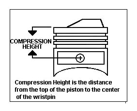
The compression height is the distance from the center of the pin hole to the deck of the piston. Ross custom pistons are available in any practical compression height to compensate for stroker or destroker cranks, long rods, or blocks which have been milled excessively, etc.
To calculate the compression height, please use the following formula:
- Block height minus 1/2 the crank stroke, minus the rod length, minus the deck clearance
(amount piston is “in the hole”). - For example, a 350 Chevy engine with a stock 3.480 stroke, stock length 5.700 rod,standard .017 deck clearance and standard 9.025 block height would be:3.480 stroke divided by 2 = 1.74
- 9.025 – 1.740- 5.700 – .017 = a compression height of 1.568
Ross Forgings
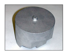
Ross has one of the most complete selections of general purpose and specific use forgings in the entire custom piston industry. We make pistons from 2.283″ (58 mm) through 6.190″ (157.2 mm) diameter for hollow dome, flat top and dish top applications. As can be seen in the photo, the lack of external features on the ROSS forging allows us complete freedom in machining special features for your pistons.
Since 1985, all Ross Racing Pistons have been forged from 2618 billet bar stock and have been heat treated and aged to a T61 condition (2618-T61). 2618-T61 is the material that is used when fatigue resistance and durability are of prime importance by all premium racing piston manufacturers. This material has less than 1% silicon particulate content. High silicon content pistons (forged from 4032 or MS75) will not stand up to the most extreme stress placed on many racing pistons. If a crack starts to form in a high silicon piston it will continue until the piston experiences a catastrophic failure. Simply stated, adding sand to the aluminum only makes it more brittle. In the rare instance of a 2618-T61 piston cracking, the crack will continue to an area where the stress is not as great and will then stop. Another advantage of 2618-T61 over the high silicon pistons is the ability to keep its shape under extreme pressure and high RPM’s. “Skirt Shrinking” is not a problem with ROSS Racing Pistons.
Gas Ports
Many Ross Racing Pistons are custom made to the customer’s specifications simply because no one piston design is correct for all applications. Different types of racing require different piston designs. Not only does the type of racing, head style, induction system, fuel and camshaft specifications affect the design features of a racing piston, but different engine types have their own needs.
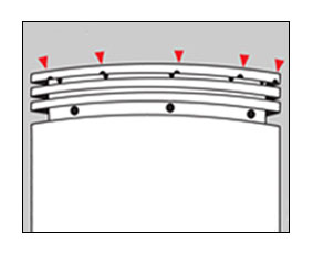
Gas ports allow cylinder pressure to go directly behind the top ring and aid in sealing. Gas ports are very effective when used with tight ring grooves and high ring positioning.
Lock Removal Indents
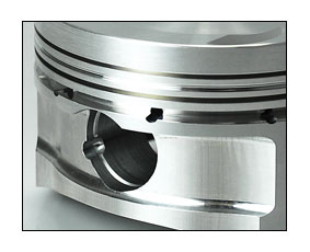
Everyone likes double Spirolox for piston pin retention because they work so well but “no one wants to take the damn things out!”.
All Ross Custom pistons are available with Lock Removal Indents at no extra charge. They make lock removal a snap! Just insert a small screwdriver behind the locks and pop them out. To insert the lox into the piston, simply pull the lox apart and spiral them into the groove.
Unless otherwise specified custom pistons will be manufactured for Spiro Locks.
Pistons For Nitrous Engines
Nitrous places extreme demands on the pistons. For this reason, ROSS uses a different design criterion for pistons which will be used in nitrous engines. If you are going to run Nitrous in your engine, be sure to advise ROSS of this at the time of your order.
Also, please specify the approximate horsepower rating of the system you plan to use.

Pin Oilers
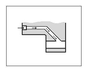
Ross Pin Oilers scrape oil from the cylinder wall and force feed it to the pins. On designs which have a high pin placement due to long strokes and/or long rod lengths, Ross will angle drill the pin oilers.
This operation is included on each custom piston at no additional charge, unless otherwise ordered.
Ring Grooves
Ross Racing Pistons with engine bore sizes of 3.500 (90mm) and above can be machined for any popular ring combination at the time of manufacture.
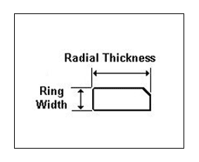
All compression ring grooves at ROSS are machined to the Society of Automotive Engineers (SAE) D-Wall specifications (except dykes rings which have a radial thickness of .170), unless the customer requests otherwise, or ROSS supplies the rings.
The radial thickness can easily be determined by using the following formula:
- Radial Thickness = Bore Diameter divided by 22
- For example: 4.250 bored divided by 22 = .193
- The radial thickness of a 4.250 bore D-Wall ring is .193
This is the standard depth used by leading ring manufacturers such as Childs and Albert, Speed-Pro, and Total Seal. ROSS STRONGLY recommends that you have us supply the rings for all custom pistons that are manufactured for a bore size of 3.500 (89mm) or smaller. If you insist on supplying the rings, you must give us the ring width and radial thickness on all three rings. In lieu of this information we can not accept “stock” or ring manufacturers part number.
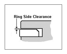
Ring Side: (or lateral) clearance is the measurement of the space between the sides of the piston
groove and the ring.
Unless otherwise ordered, Ross will machine all pistons for a side clearance of .002 to .004. Some engine builders prefer to have us reduce the side clearance (especially with gas ported pistons), however under no circumstances do we recommend less than .001.
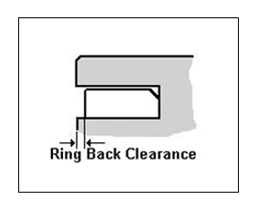
Ring Back Clearance: can best be measured by pushing the ring into the piston ring groove until it bottoms against the root of the groove.
The amount that the face of the ring is below the ring lands is the ring back clearance. It should not protrude beyond the lands when the ring is bottomed in the groove. All Ross compression ring grooves are machined for approximately .004 back clearance unless otherwise ordered. Ross will machine special groove widths or depths at no additional cost.
Ring Spacing
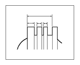
On all Ross Custom made pistons, you may specify the amount of spacing between the ring grooves.
In most instances, moving the rings up higher (thin lands) on the pistons will allow the pistons to be lighter, as the side mill cut can then be wider. Care must be taken not to make the ring lands too narrow (especially the top land) as detonation or high cylinder pressure can break thin lands. We feel that in most instances the customer should “trust our judgment” about the ring spacing.
Valve Pockets
Valve pockets will be custom machined to work with your camshaft and valves. A Ross Piston valve pocket depth is measured vertically from the piston deck to the bottom of the valve pocket (NOT at the angle of the valve).
CAUTION: Due to the acceleration ramps now being used by many camshaft grinders, the gross lift of the camshaft has little to do with the valve pocket depth. To ensure that the intake valve pocket depth will be correct, we MUST have the information below AND the amount that the intake valve is proud or recessed in relation to the surface of the head. In the event that you cannot supply this data, we will make every attempt to cut the pockets correctly based on our past experience; we will in no way be responsible should your valve to piston clearance be incorrect.
